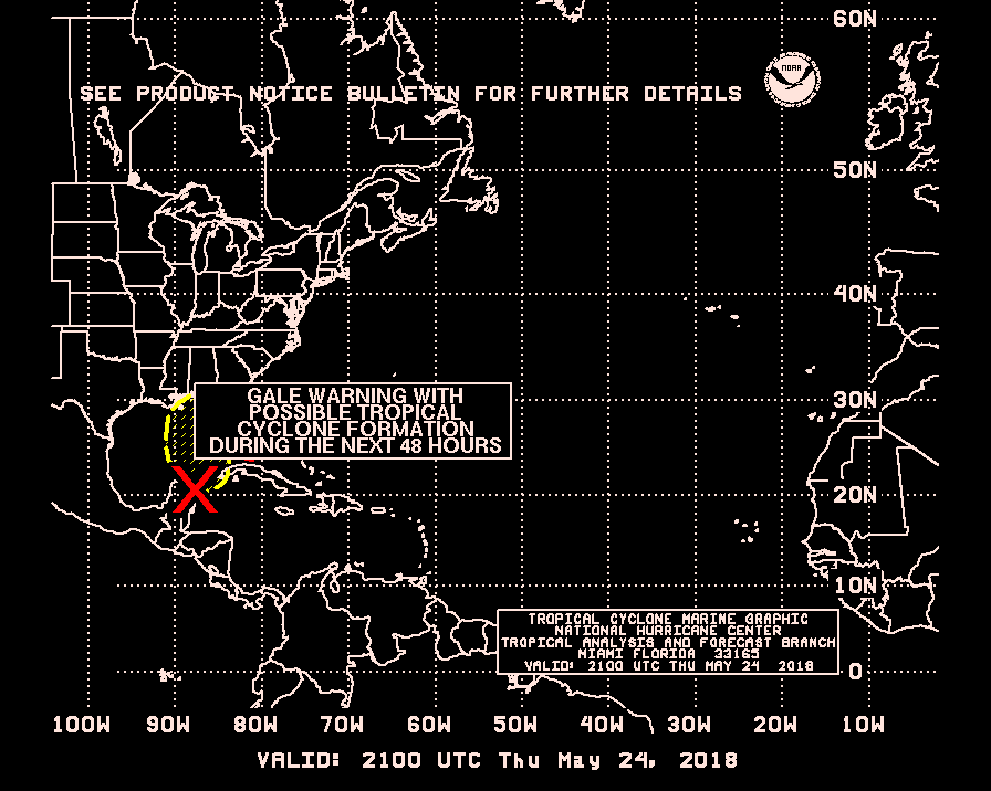
Last week we posted about M Khanfar's YouTube video that showed how to decode Es'Hail-2/QO-100 DVB-S2 on Ubuntu with the LeanDVB decoder. However, the method he showed was not in real time as it involved recording an IQ file in GQRX first, then decoding that IQ file. Similarly we also posted last week about a Windows based real time decoder.
M Khanfar recently wrote in again and wanted to show that real time decoding is possible with LeanDVB. The method is to simply pipe the output of the rtl_sdr command line decoder in LeanDVB, and then into VLC. He notes that his PC isn't actually fast enough to decode in real time without lag, but a modern i5 CPU would work well. The actual terminal command is shown in his YouTube video description.
This is Realtime live DVB-S2 Decoding done , without need to record .RAW file , its live and easy method by one click ! In this video i decoding 2MS symbol rate from wideband transponder of QO-100 beacon , you can decoding 1MS , 0.5MS , 333KS , 125KS symbol rate ! The lower Symbol, the faster speed for decoding! , the Amateurs operators on QO-100 Uplink DATV DVB-S2 at 0.5 , 333 , 125Ks , so its easy to Live Decoding Now ! With very low SNR ! , so the normal SDR can coverage wideband beacon of 2Ms symbol and all Ham uplink ! , if you have an SDR that can coverage 27.5 mb of bandwidth, so you can easy decoding Live a standard commercial satellite channels! But it need a high speed Pc .
The Es'Hail-2 satellite is positioned at 25.5°E which is over Africa. It's reception footprint covers Africa, Europe, the Middle East, India, eastern Brazil and the west half of Russia/Asia. There are two amateur transponders on the satellite. One is a narrow band linear transponder which uplinks from 2400.050 - 2400.300 MHz and downlinks from 10489.550 - 10489.800 MHz. Another is a wide band digital transponder for digital amateur TV (DATV) which uplinks from 2401.500 - 2409.500 MHz and downlinks from 10491.000 - 10499.000 MHz.
Daniel's ground station uses a LimeSDR Mini running on a Beaglebone Black. A 2.4 GHz WiFi parabolic grid antenna is used to transmit to the satellites digital amateur TV uplink. In order to generate enough power for the uplink transmission a GALI-84 amplifier chip is cascaded with a 100W power amplifier. All the electronics are enclosed in a watertight box and placed outside.
A LimeSDR Mini Based Es'Hail-2 DATV Uplink Ground Station
Russian weather satellite Meteor M2 is a popular reception target for RTL-SDR radio enthusiasts, as it allows you to receive high resolution images of the Earth. However, currently it appears to be exhibiting orientation issues, causing off center and skewed images and sometimes poor/no reception. Russian blog "aboutspacejornal", writes that the orientation of the satellite can sometimes be restored presumably by a reset command from Earth, but shortly after goes back into uncontrolled rotation.
These sorts of off-axis images were commonly received from the older decommissioned Meteor-M1 satellite, which woke up from the dead in 2015. The resurrection was speculated to be from the batteries shorting out, allowing power to directly flow from the solar panels while in full sunlight. These days Meteor-M1 is no longer transmitting.
Hopefully Meteor-M2 can be fixed, but if not, Meteor M2-2 is due to be launched on July 5 which should also have an LRPT signal that can be received easily with an RTL-SDR. Hopefully the launch is more successful than the November 2017 launch of Meteor M2-1 which unfortunately was a complete loss as it failed to separate from the rocket.
The United States Geological Service maintains over 8500 "Gaging stations" in bodies of water all over the country. Gaging stations are devices that are used to measure environmental data such as groundwater levels, discharge, water chemistry, and water temperature. What's interesting is that they all upload their data in real time to GOES satellites - the same satellites that we can use with an RTL-SDR to receive weather images of the entire earth. The data is then downlinked in the L-band to the USGS scientists via a protocol known as DCP (Data Collection Platform).
In the latest SignalsEverywhere video, Corrosive investigates how these stations work, and how we can receive the downlink at 1.68 GHz with a simple Inmarsat L-band antenna. While a fully functional decoder is not yet available, Corrosive notes that one called goes-dcs is currently being worked on.
USGS Gaging Station | Satellite Uplink to GOES and DCP Messages
Lightsail-2 is a solar sail experiment which successfully launched on a Space-X Falcon Heavy on 25 June, and was released into orbit on July 2nd. A solar sail is a type of spacecraft that uses a large metallic foil to create propulsion via photons from the sun hitting it. Lightsail-2 is still undergoing testing, so it has not yet deployed it's solar sail, but recent updates indicate that it is healthy.
On board Lightsail-2 is a radio which is transmitting it's morse code beacon "WM9XPA" every 45 seconds at 437.025 MHz. This beacon should be able to be received with a handheld amateur radio 70cm Yagi and any radio such as an RTL-SDR. There is also an AX.25 telemetry data transmission, however although the beacon structure is available we are not aware of any publicly available decoding software.
One difficulty in receiving Lightsail-2 is that it is in an orbit inclination of only 24 degrees. So only locations with a latitude between 42 and -42 degrees will have a chance at receiving it. You can see the solar sail's current location at N2YO. Clicking on the 10-day predictions button will give you pass predictions for your location.
On July 5 the Russian Meteor M N2-2 weather satellite was successfully launched into orbit and appears to be healthy. The LRPT weather camera signal is not yet broadcasting however, and we expect it to still take roughly 1-2 months before it begins (if all goes well) as satellites typically run through a long list of qualification tests before becoming operational. During this time there may be broadcasts of test patterns that can be caught. Meteor M N2-2 can currently be tracked in Orbitron and online at N2YO.
To try and dispel any confusion over the naming scheme, "Meteor M N2" is the currently operational LRPT satellite. "Meteor M N2-1" unfortunately failed in 2017 as it did not separate from the rocket. "Meteor M N2-2" is the new satellite which has just been successfully launched. Meteor M N2 and M N2-2 is often abbreviated as just "Meteor M2" and "Meteor M2-2". In the past there was Meteor M N1, but this satellite is no longer operational. We have upcoming launches for Meteor M2-3, M2-4, MP-1 and M3 to look forward to which are scheduled for 2020 and 2021.
Back on June 28 we posted about how Meteor M2 was experiencing orientation issues for a few days. Those issues appear to have been rectified now. Hopefully if M2 remains stable we'll have two Meteor LRPT weather satellites to receive alongside the three NOAA APT satellites.
If you're interested, there were also several other payloads onboard the rocket carrying M2-2, including a low cost Czech experimental cubesat called Lucky7 whose telemetry can be received in the amateur radio band at 437.525 MHz. There is an onboard camera too, but no details on how to receive it yet.
Galileo is a European Union owned satellite navigation system. Galileo was created so that the EU does not need to rely on the US GPS or the Russian GLONASS satellites, as there is no guarantee that these systems won't be purposely turned off or degraded by their governments at any time.
Unfortunately since July 11 the Galileo system has been out of service. Not much information about the outage has been provided, but it appears to be related to problems with the Italian ground based Precise Timing Facility which consists of two ultra high precision atomic clocks that keep the Galileo systems' reference time. (We note that recently within the last few hours of this post, most satellites seem to have come back into operational status, but the EGSA website still reports an outage.)
Over on his blog, Daniel Estevez has been using his LimeSDR and a small patch antenna to gather some more information about the outage directly from the Galileo satellites. His investigations found that the modulation and signal itself are still working correctly. However, by using the GNSS-SDR software to investigate the signal data he was able to obtain the ephemeris, and see that the ephemeris is stuck in the past. The ephemeris data is used to calculate compensations for orbital drift and without frequent ephermis updates, orbital errors add up within hours resulting in poor positioning accuracy. In order to generate the ephermis, the Precise Timing Facility must be operational.
Daniel's post goes into further technical details about the information he's collected, and it's definitely an interesting read. One interesting bit of information that you can read from his post explains why the service has gone from initially just heavily degraded accuracy from July 11, to completely nonsense results from July 15 onwards.
The Software Defined Radio Academy YouTube channel recently uploaded an interesting talk by Alex Csete (creator of the popular GQRX and GPredict applications), and Sheila Christiansen. Their presentation discusses their work with the European Space Agency (ESA), Libre Space Foundation and how they are running SDR Makerspace's that are helping students create and track cubesats. During the talk Alex and Sheila also describe various SDR hardware, and how they test them for their purposes.
SDR Makerspace (https://sdrmaker.space) is a collaboration between the European Space Agency and Libre Space Foundation, with the objective of bringing innovative open-source SDR technologies to space communications.
Space is a complex environment. Attempting to incorporate SDRs into complex subsystems of space missions without sufficient understanding of the technology can add unnecessary risks and uncertainties to the mission. SDR Makerspace aims to bring open-source SDR technology to the space industry, focusing on the practical aspects of satellite communications, so as to reduce such risks.
Makers, open-source hackers, SDR enthusiasts, and researchers are collaborating on SDR hardware and software activities, focusing on rapid prototyping and development of reusable, open-source SDR components for future CubeSat missions.
The collaboration consists of many activities, which are organized into three main elements: development of reusable GNU Radio components, research and development in cutting edge technologies like AI/ML, and testing of SDR hardware and software.
Current activities are presented with a focus on the testing of the hardware and software. An overview of the investigation into the characteristics, such as, performance under realistic conditions, damage by radiation to essential parts, functionality of FPGA toolchains, the SDR-system’s complexity, and accessibility to the open-source community will also be covered.
Alex Csete, OZ9AEC: SDR-Makerspace: Evaluation of SDR boards and toolchains
On this episode of SignalsEverywhere on YouTube Corrosive shows off several antennas that can be used for Inmarsat and Iridium satcom reception. His video shows off a commercial Inmarsat branded satlink antenna which is designed to be used on moving ships, a grid dish antenna, a custom QFH iridium antenna made from a repurposed Vaisala radiosonde, a commercial Iridium patch, an older Outernet/Othernet Iridium patch and a custom Iridium patch that Corrosive built himself.
Satcom Antennas for L-Band Reception via RTL SDR
A few days prior Corrosive also released a new episode of his podcast. In this episode he interviewed Derek a student from The University of Michigan who is working on the MiTee CubeSat. The MiTee cubesat is a small experimental satellite that will explore the use of miniaturized electrodynamic tethers for satellite propulsion.
Lucky-7 is a Czech cubesat that carries some interesting sensors including a low power GPS receiver, a gamma ray spectrometer and dosimeter and a photo camera. The creators also claim that it is "probably the lowest-cost scientific space mission in human history". It was recently successfully launched and orbited together with the Meteor M2-2 weather satellite and several other small satellites.
"We did not build just another satellite. It is a flying laboratory. The satellite is going to test something that nobody has ever done before. Thanks to our background in electronics, materials and space effects, we implemented commonly used electrical parts from automotive and IoT industry in totally new ways. Gallium Nitride power transistors used in modern electric cars do not contain insulation layer to control its conductivity. That makes them much less vulnerable against the space radiation. We fly the world's first MOSFET-free power supply ever built for small satellites. The LED lighting industry has been used to make composite aluminum radiation shields for us. It is very cheap, lightweight and it naturally increases the mission lifetime," says Jaroslav Laifr, the CEO and founder.
If all goes well, the team will be able to measure the in-situ radiation background by miniature onboard Dosimeter and monitor the health of key subsystems, such as communication or data storage by complete satellite telemetry. The experimental Gamma Spectrometer payload informing about the energy of incident radiation will be able to detect Gamma Ray Bursts from distant galaxies. The platform also contains the VGA camera to demonstrate the data transfer capability. It may capture the first colour images ever taken by Czech satellite, possibly detecting the aurora glow. Such pictures would be greatly utilized for the outreach and inspire a new generation of scientists and engineers.
Daniel Estesvev has recently added a Lucky-7 decoder to gr-satellites, and has uploaded a post explaining some technical details on how he created the decoder. With this decoder, anyone with an SDR and appropriate antenna should be able to receive and decode the telemetry (no word on camera images yet). He writes that "Lucky-7 transmits 4k8 GFSK telemetry in the 70cm band. It uses a SiLabs Si4463 transceiver with a PN9 scrambler and a CRC-16. You must use FM mode to receive this satellite (437.525MHz)."
CubeSat companies like Sky Fox Labs are also tracking the satellite, and are tweeting results.
Lucky-7 #CubeSat Gamma Ray Spectrometer (0.3-3 MeV) data from first 1 hour of operations were compiled. It shows the contiuum in energy spectra as expected, no line spectra detected (obviously, there is no flying Cesium nearby). It corresponds to Dosimetry measurements!
Over on his YouTube channel Adam 9A4QV has uploaded a short video that demonstrates his 2.4 GHz homemade helical feed designed to be used with a reflector (prime feed satellite dish) for QO-100/Es'Hail-2 satellite reception. The antenna is made from an old can, 2-turns of copper wire, and a plastic insulator to hold the turns in place. The two turns are wound in left hand circular polarization (LHCP), because when used with a satellite dish reflector it will result in right hand circular polarization (RHCP), which is the polarization QO-100 uses.
One of the most important parts of the video is when Adam shows how he matches the antenna to 50 Ohms. He notes that without matching the antenna won't work properly, and the return loss will be about 8 dB or even less, resulting in poor performance. With matching he obtains 30 dB return loss.
If you've been following our blog, or have your own RTL-SDR based weather satellite station, then you'll know that the NOAA-15 APT satellite has been experiencing issues lately. There appear to be problems with it's camera scan motor resulting from it running low on lubrication. This is fully understandable as the satellite is 21 years old and well past it's expected life span. The satellite appears to be working some days, and producing garbage image other days.
When NOAA-15 fails for good, don't feel too bad as we still have NOAA-18 and NOAA-19, the Russian Meteor M2, and Meteor M2-2 satellites, and the GOES satellites, all of which can be received by an RTL-SDR. Several new weather satellites are also planned for 2020 and onwards.
GOES 16/17 and GK-2A are geosynchronous weather satellites that transmit high resolution weather images and data. In particular they are far enough away from the earth to be able to take beautiful 'full disk' images which show the entirety of one side of the Earth. As these satellites are in a geosynchronous orbit, they can be counted on to be in the same position in the sky at all times, so no tracking hardware is required and images can be pulled down constantly throughout the day without having to wait for a polar orbiting satellite to pass over like you would with the NOAA APT or Russian Meteor satellites.
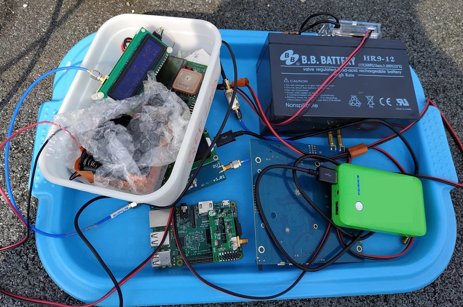
With a low cost WiFi grid dish antenna, LNA and RTL-SDR dongle, any home user within the footprint of one of these weather satellites can receive and decode live images directly from the sky. Setting up a station is overall not too difficult, but it can be a bit fiddly with a number of steps to complete. Below is our comprehensive guide. We'll show how to set up a self contained Raspberry Pi based system with goestools (free), as well as a guide for the Windows PC software XRIT decoder (US$125).
We've attempted to make the tutorial as newbie friendly as possible, but we do need to assume basic RF knowledge (know what antennas, SDRs, coaxial, adapters etc are), basic Linux competency for the goestools tutorial (using the terminal, using nano text editor), and basic Windows competency for the XRIT decoder tutorial (unzipping, editing text files, running programs).
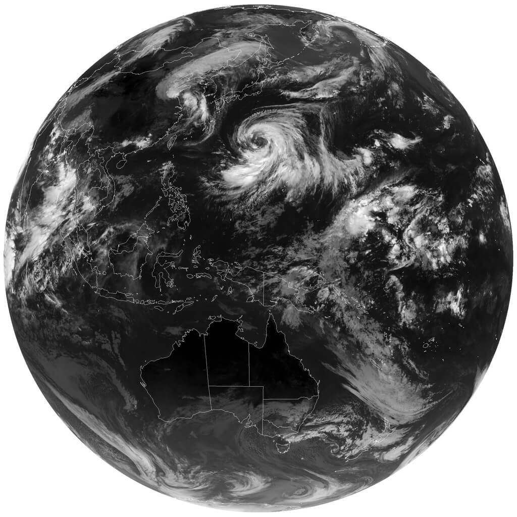
A full disk false color image received directly from the GOES-17 satellite with an RTL-SDR. Click for the full size image (14MB).
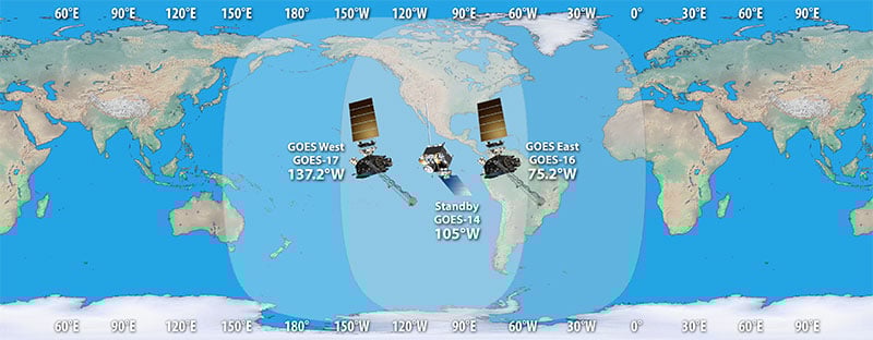
There are two fourth generation NOAA GOES satellites that are currently active, GOES-16 and GOES-17. These transmit HRIT signals, and also transmit shared data from the older third generation GOES 15, and Japanese Himiwari8 satellites. At the moment GOES-16 and GOES-17 are producing full disk images every 30 minutes, and close up "mesoscale" shots of the USA every ~15 minutes. GOES-16 (aka GOES-R) and GOES-17 (aka GOES-S) are also known as GOES-EAST and GOES-WEST respectively. At least one of these satellites can be received from North/South America, Canada, Alaska/Hawaii, New Zealand, Eastern Australia and some pacific islands.
There is also the older generation GOES-15 and GOES-14 which have been placed in standby orbits. These transmit LRIT signals which provide images at a slower rate.
GOES 16/East and GOES 17/West Signal Footprint
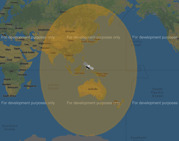
There is also the Korean GK-2A (GEO-KOMPSAT-2A) satellite which is very similar to the GOES satellites. GK-2A covers countries like India, Asia, Australia, New Zealand and parts of Russia. Note that you may have previously heard of the COMS-1 satellite which used to cover this area. Since July 2019 COMS-1 was replaced by GK-2A. Unlike GOES, GK-2A images are encrypted. However it has been found that "sample" encryption keys found online in demo code work just fine.
GK-2A contains both LRIT and HRIT channels, but at the moment only the LRIT channel can be decoded with the currently available software. The LRIT channel sends full disk IR images every 10 minutes in 2200 x 2200 resolution. Compared to the 5424 x 5424 resolution GOES full disk images, this is smaller, but still large enough to be interesting.
Note that even if HRIT decoding is added by the current software, you would require an Airspy or other wideband SDR as the GK-2A HRIT signal bandwidth is 5 MHz. Also since the HRIT bandwidth is so wide, the signal strength is reduced, meaning that you'll need a larger dish. People who have received the HRIT signal note that a 3M+ sized dish seems to be required.
GK-21 (GEO-KOMPSAT-2A) Footprint
You might ask why bother receiving these satellite images directly, when you can get the exact same images from NOAA at https://www.star.nesdis.noaa.gov/GOES/index.php. Well, you might want to set up your own station to be independent from the internet, or you live in a remote location without internet, or maybe just for the fun and learning of it.
To set up a receiver for GOES 16/17 HRIT or GK-2A LRIT you'll need to purchase a dish antenna such as a cheap 2.4 GHz WiFi antenna, an RTL-SDR, GOES LNA, and a Raspberry Pi if using goestools, otherwise a Windows PC can be used. The total cost could be anywhere from $150 - $200 depending on what pieces you already have available.
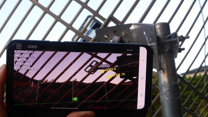
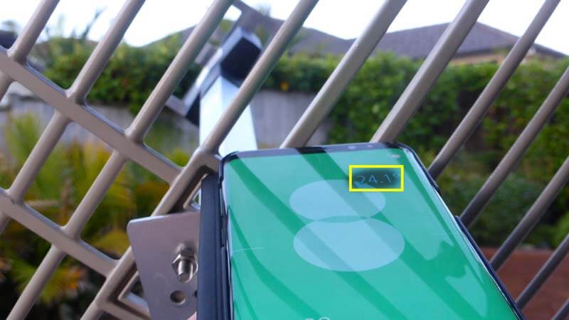
Before we start the tutorial, you might want to use an augmented reality Android app like "Satellite-AR" to get a rough idea of where either GOES 16/17 or GK-2A (GEO-KOMPSAT-2A) is in your sky, and if receiving them is even feasible for your location. You'll need to find an area on your land where you can mount a small satellite dish with an unobstructed line of sight view to the satellite (no trees or buildings can be blocking the signal path). If the satellite is low on the horizon (below 25 deg elevation), then things get a little more difficult as you have more obstructions and a weaker signal. But it can still be done, and we're able to routinely get good results at 24.5 deg elevation.
Note that for Europe and Africa, unfortunately there are no satellites that can be received easily with an SDR and LNA. But you might instead be interested in the EUMETCAST service, which can be received from EUTELSAT 10A (Ku band), Eutelsat 5 WEST A (C Band) and SES-6 (C Band) . To receive this service you'll need a DVB-S2 receiver and a satellite dish with appropriate band LNB. You also need a license keys and software which all together cost €100. EUMETCAST reception is not covered in this tutorial, instead see this video.
Hardware Required
An RTL-SDR Blog V3 dongle. (US$21.95)
Some other RTL-SDRs will work too, but confirm that the dongle you purchase has a bias tee built in. (All RTL-SDR Blog V3 dongles have a bias tee). Alternatively, you can purchase an external bias tee.
Note that most of the cheapest generic RTL-SDRs do not work properly at 1.7 GHz due to overheating issues that we discovered can cause problems with reception above roughly 1.5 GHz. Only RTL-SDR Blog V3, E4000 and other dongles with cooling fixes will work.
An Airspy One can also be used with goestools on Linux and XRIT Decoder on Windows. An SDRplay unit can be used with XRIT Decoder on Windows only.
A low noise amplifier (LNA), preferably with filtering. (US$34.95) An LNA is absolutely required to receive the GOES signal. The LNA should ideally have a noise figure (NF) below 1 dB.
Optionally, adding a second LNA after the SAWbird can help improve reception too, but then you'll need to power the SAWbird directly. If powering directly be very careful and be aware that SAWBird products have a minor design flaw where if you use external power it will output power to the dongle side as well. This could destroy your RTL-SDR's ESD diode and other components if you do not use a DC blocking cap.
A 2.4 GHz WiFi parabolic grid dish antenna. (US$50 - US$100) 2.4 GHz is above our intended RX frequency of 1.7 GHz, but these antennas are confirmed to still work well. Note that for reception of satellites that are low on your horizon (below 25 deg), we recommend looking for a 1.9 GHz antenna instead as these work a bit better. However we have been able to confirm that with minor modifications we can still receive the signal decently at 24.5 deg elevation with a 2.4 GHz WiFi antenna.
A 2.4 GHz WiFi parabolic grid antenna - make sure you get the kind with the largest reflector (the grid dish part) possible. The right size is around 100cm x 60cm (39 x 24 in) or larger. Also ensure that it has a metal secondary reflector. Examples Products [1][2][3]
Alternatively, if you can find a similarly sized or larger 1.9 GHz antenna, then this will work even better. But these are typically much more expensive when compared to WiFi grid antennas and sometimes difficult to find.
Other circular satellite dishes can work too, but those typically don't come with their own feed as they're designed for LNBs. If using a circular dish you'd have to design and make your own feed. If this interests you, see Lucas' cantenna feed example as a reference.
If needed, you can improve reception by extending the parabolic grid dish reflector size with metal chicken mesh.
A mount for the parabolic dish. (US$39.99) This could be a portable antenna tripod, or a more permanent mast. Example product [1].
Coax adapter for the parabolic grid. (US$5.99) The grid antenna will typically come with an N-female connector. So look for an N-Male to SMA Male adapter, to be able to fit the RTL-SDRs SMA female input. Example product [1].
Low loss RG6 coax cable, or an active USB extension cable.
Either use low loss coax cable or a USB extension cable to get the LNA and/or RTL-SDR out to the antenna. An active USB cable will be required for longer USB runs. You may have to build a waterproof enclosure if mounting permanently outside.
To ensure good signal strength, the LNA must be connected right at the antenna - there should be as little coax as possible between the LNA and antenna.
We strongly recommend using as little coax as possible after the LNA too. The SAWbird LNA doesn't have enough gain to push the signal through long runs of coax. If you're forced to use long runs of coax, use a secondary LNA. Preferably use a USB extension cable to reduce coax runs.
A Raspberry Pi 3/4 + 8GB or larger SD card. (US$40 - US$100) Setting up the software on a Raspberry Pi 3/4 is the easiest way to create a permanent monitoring solution. Example product [1].
(Optional) You may want to have an external hard drive connected to the Pi for image storage as you'll be getting 1-2 GB of images a day.
(Optional) Weather proofing boxes.
If you're planning on running the system permanently, you'll want a water proof box to house your LNA and/or RTL-SDR.
(Optional) Additional Cooling
Avoid running the RTL-SDR or Raspberry Pi in direct sunlight, or in very hot areas. The RTL-SDR V3 has passive cooling, but if the RTL-SDR overheats from direct sunlight or a lack of surrounding airflow you will probably begin to see the viterbi error rates rising, and eventually failed reception. If you experience heat related issues, shield the SDR from direct heat, and/or use some sort of cooling system with a heatsink and fan. Even a small amount of airflow can help significantly.
Setting Up the Hardware and Modifying the Antenna
Overview of Hardware Connections and Pieces
Connect the SAWBird to the antenna, and then the RTL-SDR. Double check that you have the SAWBird the correct way around, with the "OUT" side connected to the RTL-SDR, and the "IN" side connected to the antenna. Keep the SAWBird as close to the antenna as possible. You can use a short run of coax between the SAWBird and RTL-SDR, but keep this to a minimum too. Instead of coax, use long active USB cables, or keep your Raspberry Pi close by.
GOES satellite signals are vertically polarized, so the secondary reflector and feed should be installed vertically, not horizontally.
For 2.4 GHz WiFi antennas, the secondary reflector might be curved. To optimize the reception for 1.7 GHz mount the secondary reflector concave side facing outwards.
You can improve the antennas performance at 1.7 GHz by adding a spacer to the secondary reflector so that it sits about 2.5 to 3.5 cm away from the primary reflector. Here is a video that demonstrates this idea. To mount the spacer you'll need to find a longer screw of the same size.
Modifications for 2.4 GHz WiFi Antennas to improve 1.7 GHz Reception
.
Pointing the Antenna
The antenna must be positioned outside. The signal is very weak so it will be very difficult to receive through a window.
Elevation: Angle up/down Azimuth: Angle left/right Polarization/LNB Skew: Rotation angle of the dish
Setting the Elevation and Azimuth
You'll need to point the grid antenna fairly accurately at the GOES satellite. If you are out by even 1-2 degrees, the signal will not be seen, or be weak. Use the website dishpointer.com to determine the Elevation and Azimuth that is required to point your dish, or simply take note of the line pointing towards the satellite and align the dish with features from your house. Note that on dishpointer GOES-17 is listed as 137.2W GOES-S (may change to GOES-17 in the future), and GOES-16 is listed as 75.2W GOES 16.
For now you can just point it roughly as we'll fine tune alignment later.
Dishpointer example. Line the dish up with the driveway corner.
You can also use an augmented reality Android app like "Satellite-AR" to get a rough direction of the satellite. But this cannot be trusted for accuracy as the compasses on smartphones are often not very accurate. We recommend using a standard magnetic compass to help point by using the Azimuth (magn.) information from dishpointer.
Using the Satellite-AR Android App to check the rough direction of GOES-17.
To determine the elevation you can use a bubble leveling tool, or an Android app like "Bubble Level".
NOTE: We may be slightly wrong on this polarization info as the polarization might also be dependent on the satellites's antenna oritentation. This info seems to hold true for GOES satellites, but not GK-2A. If any one can confirm, please let us know.
Once you have the Elevation and Azimuth of the dish approximately correct, you'll need to adjust the rotation (aka skew) of the dish in order to match the polarization of the satellite at your location. Dishpointer will tell you exactly what rotation angle to use, and in which direction, under the "LNB Skew" information.
If you are on the same longitude as the satellite your skew will be zero, and no rotation will be required. However, those further away on the longitude plane will require their dishes to be rotated. Most WiFi and 1.9 GHz grid dish antennas only allow you to rotate in 45 deg angle increments, so just choose the closest increment to what is given in dish finder.
In the image below Example 1 shows a user in California, pointing at GOES 16. Dishpointer shows that the required rotation is 42.2° CCW. So standing behind the antenna you would rotate the dish by 45° so that the left side is closer to the ground. Example 2 shows a user in New York pointing to GOES 16. Here the required rotation is almost zero, so no rotation is required. Keep the dish horizontal. In Example 3 the user in is Auckland, New Zealand pointing at GOES 17. Here the rotation is 44.6° CW, so the user would rotate the dish with the right side being lower.
Note that for GK-2A we found that the LNB skew given by dishpointer appears to be reversed in terms of the required rotation direction. We're not sure why, but may have something to do with the way the antenna is oriented on GK-2A.
Now that you have your dish pointed in the correct direction we'll need to fine tune the positioning to detect and maximize signal strength. When fine tuning the alignment of the dish you'll need to run a program like SDR#, and keep an eye on the spectrum and waterfall while making fine adjustments to your dish. If you can't see your PC screen while positioning the antenna, it will be very difficult to confirm and tune reception.
To make it easier if you don't have a laptop, install the Teamviewer application (or any alternative like VNC) on your desktop PC, and run SDR# with the dongle and LNA connected to the antenna. Then view the PC's screen on your mobile device using the Teamviewer App, and slowly move the dish around until you see the HRIT/LRIT signal. If using the RTL-SDR V3 make sure that you activate the bias tee first using the bias tee software (see Feature 2 on the V3 guide).
Try to get the signal as strong as you can, but do not worry too much about ultra fine tuning. Later when running the software we will optimize the reception even further using the viterbi error correction rate produced by the decoder software.
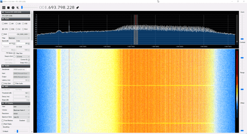
The image below shows what reception of a GOES 16/17 HRIT signal looks like. The large bump on the right is the HRIT signal which contains all the weather image data. The narrowband signal on the left is EMWIN, which contains simple text data and simple weather fax type images.
What GOES-17 looks like in SDR# on an RTL-SDRChecking GOES Reception Remotely via Teamviewer
Note that there are sometimes brief periods of a few minutes where the GOES signal is idle. During this time the HRIT signal level will be a bit lower.
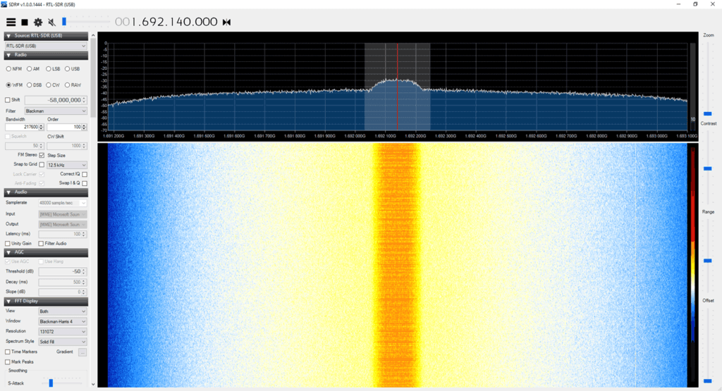
The image below shows that the GK-2A LRIT signal looks like.
GK-2A LRIT Signal
Sun Interference Note: During the day time while the sun is up reception signal strength can be reduced, sometimes even resulting in no reception at all. If you cannot find the signal during the day, try again later at night after sundown. Interference appears to be the worst when the sun is behind the satellite.
When the sun is behind the satellite, we cannot receive the signal at all.
Raspberry Pi goestools Linux Software Install and Setup
For the Raspberry Pi we will use the goestools software suite which decodes and generates images for us. Goestools is made for Linux, but it might be possible to compile and run on Windows/MacOS too, although we're unaware of any successful attempts. The easiest way to set it up is to install it on a cheap Raspberry Pi 3/4.
Connect the Pi to a monitor, log in with username: pi and password: raspberry, then run "sudo raspi-config" and set up your WiFi connection.
If using an Ethernet cable you do not need to set up WiFi.
Find the IP Address of the Pi either via Method A or B
Using a monitor, open a terminal on the Pi and find it's IP address by using the command "ip addr" without quotes. Or,
Open your network routers' configuration page on any PC, and search the settings for a list of connected devices. You should be able to see the Raspberry Pi listed there, with it's IP address.
Now you should connect to your Pi from a PC on the same network using any SSH software such as PuTTy.
At this point we recommend following the excellent goesrecv software installation guidelines written by Aleksey Smolenchuk (lxe). Go through steps 1 - 6. It is a simple matter of copy and pasting the commands into the SSH terminal.
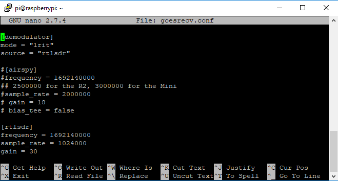
However, on step 6 of Aleksey's guide, we recommend changing the sample_rate to 2000000. We've found that higher sample rates often cause goesrecv to require multiple restarts in order to get a lock on the frequency. Also if you're using an RTL-SDR V3 enable the bias tee and increase the gain to 30:
sample_rate = 2000000
gain = 30
bias_tee = true
Running the Software and Fine Tuning the Antenna
Later we will create a script that automatically runs the software on boot. However, for now let's first test it.
To run the software open two separate SSH terminals on your main PC using PuTTy or a similar SSH terminal program. Connect to the Raspberry Pi's IP address, port: 2222 with SSH. Log into the Pi with the default username/password: pi/raspberry. In the first terminal run the command:
goesrecv -v -i 1 -c ~/goesrecv.conf
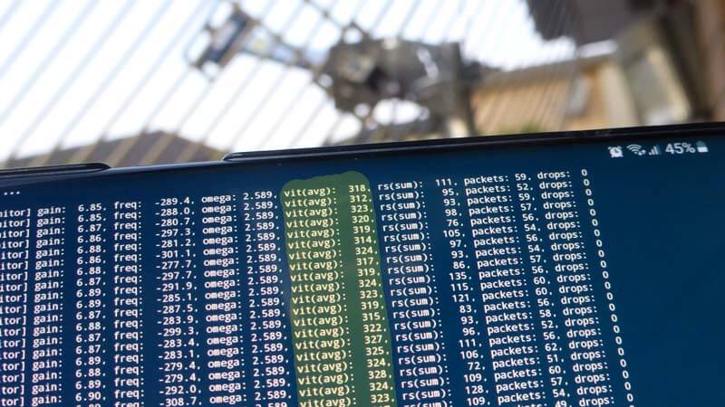
At this point you'll see a bunch of data begin to scroll by. The important thing to look at is the "vit(avg) and "drops" data. You should be seeing zero drops, and a vit(avg) of below 500, and ideally below 400. If you are seeing higher vit(avg) values and drops, you must realign and improve your dish antenna's reception. If you're getting a vit(avg) of around 400 - 600 you may be able to proceed, but some images may be lost or incomplete if you are seeing frequent drops. Anything above 600 and you probably won't be able to get any images.
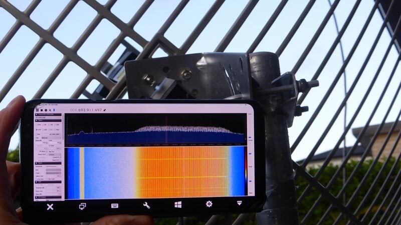
Signal Optimization TIP: To further optimize the signal, install an SSH terminal like "JuiceSSH" on your mobile device. Run the above goesrecv command on your mobile, and adjust the antenna until the vit(avg) reading is as low as possible. You may need to restart goesrecv after a large adjustment for it to get a better lock on the frequency.
Remotely checking vit(avg) with JuiceSSH on Android.
Finally, if you have vit(avg) below 500 and are seeing zero drops, run the following command in the second PuTTy window.
At this point images will begin to download. Check back in 15 minutes and see what you've received. All images are written to the folder specified by the --out flag, in this case /home/pi/goes.
During testing you can easily transfer files out of the Pi to a Windows machine on the same network using a program called WinSCP. When starting WinSCP, simply select "New Site", choose the SCP file protocol and enter the Pi's IP address. You can then browse the Pi's directories, and download the image files from the folders generated in the home directory. But this is slow and time consuming, so we recommend using a more automated solution explained further below.
Also, if you wanted to, you could run goesproc on another Linux PC on your network and have the images generated on that machine. To do that, run goesproc with the Raspberry Pi's IP address in the --subscribe flag on the networked machine.
Browsing Images in a Web Browser
Note that we've had issues with Mediaweb crashing and being very slow when generating thumbnails, so we generally recommend that you use syncthing (shown below) instead.
An easier way to view the downloaded images is to install a simple folder web server like "Mediaweb" which will allow you to browse your received images on a web browser over a network connection.
Install the software using the instructions on the mediaweb Git. When installing be sure to choose /home/pi/goes as the default directory. Once installed Mediaweb will run in the background continually even after rebooting. So you can always browse your images.
Once mediaweb is installed and running, you can then browse to PI_IP_ADDR:9834 on any device connected to the same network as the Pi, and you'll be able to see the currently created folders and images (where PI_IP_ADDR is the IP Address of your Raspberry Pi).
Note that you might want to enable the thumbnail cache in /etc/mediaweb.conf, too. Remember to restart mediaweb after by using "sudo systemctl restart mediaweb".
Automatically Transferring Images to your Windows/Other Main PC
Syncthing is a program that you can use to automatically copy and sync your goes image folder with your main Windows/Mac/etc PC on the same network.
Syncthing is configured via a web interface, with default IP address of 127.0.0.1 (localhost). As we're running Raspbian Lite, we don't have a GUI and therefore can't run a web browser on the Pi. So we'll need to open the browser based configuration GUI on a networked PC. To do this we need to set the IP address of the GUI to the Pi's local network address. Edit the syncthing config, and under the <gui> entry, change the <address> value to 0.0.0.0 which will allow you to connect to the Pi's IP Address.
sudo nano /home/pi/.config/syncthing/config.xml
Syncthing config, set IP to 0.0.0.0
Save and exit with CTRL+X, Y.
Next, run "syncthing" on the command line.
Now on your main PC, open a web browser and browse to PI_IP_ADDR:8384 to open the syncthing GUI for the Raspberry Pi.
On your main PC, download, install and run the Windows version of syncthing. This will automatically open up a browser with the GUI for the Windows syncthing instance. Click on "Add Remote Device". It should be able to find the Raspberry Pi automatically, and you can double check the device ID by going to Actions->Show ID in the Raspberry Pi GUI. In the Windows GUI, simply click on the device ID, and click on Save.
Within a few seconds/minutes, the Raspberry Pi GUI should pop up with a "New Device" alert. Click on Add Device -> Save.
Still within the Raspberry PI GUI click on Add Folder. Set the folder path to /home/pi/goes, and set the label to "GOES Images". Leave the Folder ID default. Go into the "Sharing" tab, and enable sharing for your Windows machine. Click on Save.
After a few seconds/minute or two, the Windows GUI web interface should pop up with a "New Folder" alert. Click on "Add", then under "Folder Path" set where you want the image files to be copied to. Then click on save.
Wait a couple of minutes, and then it should begin syncing.
Run goesrecv, goesproc and syncthing Automatically on Boot
At the moment goesrec, goesproc and syncthing all need to be started manually whenever the Pi is rebooted. It would be better to create a system that automatically runs goesrecv, goesproc and syncthing when the Pi is booted. Then there is no need to keep an SSH terminal open and manually start the receiver and decoder whenever the Pi is rebooted.
First create two startup scripts called startgoesrecv.sh and startgoesproc.sh in your home directory.
Next create a system service that will load the script on boot, after the network service has already been loaded. We are creating two services instead of one, because we need goesrecv to start as root in order to be able to open the RTL-SDRs, and goesproc to start as user pi to make accessing the files easier later on. Also Syncthing cannot be run as root.
# Create the service to start goesrecv

sudo nano /etc/systemd/system/startgoesrecv.service

# Copy and paste the following

[Unit]
Description=Start GOES receiver after network is loaded
After=network.target
[Service]
User=root
Group=root
Type=oneshot
ExecStart=/home/pi/startgoesrecv.sh
[Install]
WantedBy=multi-user.target

# Create the service to start goesproc

sudo nano /etc/systemd/system/startgoesproc.service

# Copy and paste the following
[Unit] Description=Start GOES processor after network is loaded as user pi
After=network.target
[Service]
User=pi
Group=pi
Type=oneshot
ExecStart=/home/pi/startgoesrecv.sh
[Install] WantedBy=multi-user.target

# Create the service to start synthing
sudo nano /etc/systemd/system/startsyncthing.service

# Copy and paste the following
[Unit] Description=Start syncthing after network is loaded as user pi
After=network.target
[Service]
User=pi
Group=pi
Type=oneshot
ExecStart=/usr/bin/syncthing
[Install]
WantedBy=multi-user.target
Note that if you plan on making this a permanent station, it would be wise to connect a large external hard drive to your Pi, and save images to there. In that case you'd change the --out flag in the startgoesproc.sh to the path of the harddrive.
(Untested Idea) Even with a hard drive, you might also want to remove files and folders older than ~30 days or so to avoid running out of space. GOES16/17 transmit about 2GB of data a day so storage can run out fast. (Adjust +30 in the script below to how many number of days of images you want to keep)
The easiest way that we found was to use an online service like https://gifmaker.me. Pieterns goestools guide shows an offline Linux method involving Imagemagick, but we found it too slow to run on a Pi 3.
Then to share upload to an efficient GIF sharing site like gfycat.com.
Below is a GIF of half a day of GOES 17 false color full disk images that come in every 30 minutes.
Below is a short GIF from GK-2A with 10 minute interval images.
Raspberry Pi GK-2A goestools Tutorial
Please note that GK-2A decoding is still in it's infancy, and the decoder is still being worked on by @sam210723. He is frequently updating his modified version of goestools and his xrit-rx software for GK-2A decoding.
First install the modified goestools for Gk-2A version at https://github.com/sam210723/goestools. Compilation instructions are on the page BUT we DO NOT recommendusing the apt-get install librtlsdr-dev line in his instructions, as this will most likely install an older version without bias tee support. Instead, install librtlsdr from source as explained in Aleksei's guide. If you already installed the original goestools before then you will already have the correct librtlsdr installed. But note that running sudo make install will overwrite the original GOES goestools version. If you prefer you can just run the GK-2A goesrecv program from the build/src/goesrecv folder and not run sudo make install.
Next edit the goesrecv.conf file that you copied over with "nano goesrecv.conf". If you're using an Airspy, the conf file should already be ready, but you may want to edit it to activate the bias tee. If using an RTL-SDR, change the "source" to "rtlsdr", comment out the [airspy] settings by putting a "#" in front of them, and remove the "#" from the [rtlsdr] lines. Set the gain to 30, and bias_tee to true. CTRL+X, Y to save and exit.
Editing the goesrecv.conf file for RTL-SDR GK-2A reception.
Install xrit-rx
XRIT-RX takes the place of goesproc. First we need to download the encryption key.
You'll now have a file EncryptionKeyMessage_001F2904C905.bin.dec stored inside the xrit-rx folder. Now edit the xrit-rx.ini file with nano, and set the "keys = EncryptionKeyMessage_001F2904C905.bin.dec"
Set key file in xrit-rx.ini
Finally, open two terminal windows in PuTTy. In terminal one run the following, and confirm that you get a low vit(avg) rate, and no drops.
goesrecv -i 1 -c goesrecv.conf
In the second terminal window run the following and it will automatically begin creating LRIT files.
sh xrit-rx.sh
In order to create images from the LRIT files you need to periodically run the lrit-img.py program found in the tools folder. Once run the full disk images will be produced in the FD folder.
# Install a dependency
pip3 install pillow

# Browse to the current date
cd ~/xrit-rx/received/LRIT/20190819

# Run the program on the "FD" folder
python3 ~/xrit-rx/tools/lrit-img.py FD
Like with the standard goestools setup, you could now make these programs run on boot with systemd, and set up syncthing. You could probably also create a crontab entry to periodically run lrit-img.py.
Windows XRIT Decoder Tutorial
If you instead prefer to use Windows software, USA-Satcom (Joe) has a decoder called "XRIT Decoder". Due to certain libraries used, it is not free and is available for a price of USD $125. The price includes free future updates and access to a private groups.io forum for support and downloads.
An additional US$25 gets you an option piece of software called "XView" which is a viewer that allows you to view and filter images as they arrive. This is useful if you're creating some sort of live display. XView also has an animation feature that allows you to easily create weather movies.
XRIT-Decoder can decode GOES LRIT and HRIT data. It also appears to be somewhat compatible with GK-2A LRIT at the moment, and this is set to be improved in the future. It is compatible with the RTL-SDR, Airspy and SDRplay software defined radios.
In order to purchase XRIT-Decider you must contact him directly by email. You can also request a 30-day demo. After purchasing or requesting a demo USA-Satcom will send you activation and usage instructions.
XRIT Decoder SpyServer Setup
Note that if you are using an SDRplay SDR, you can skip this step.
For RTL-SDR and Airspy SDRs, XRIT Decoder relies on SpyServer from SDR# to provide data. SpyServer is a remote server application that supports the RTL-SDR and Airspy products. It's a part of the SDR# software package and can be downloaded from www.airspy.com.
SpyServer runs on Linux, Windows and ARM single board PCs like the Raspberry Pi. So if you wanted to you could set up a remote SpyServer on a Raspberry Pi connected directly to the antenna, and decode the data remotely on your Windows PC with XRIT Decoder.
Turn on the bias tee.
If using an RTL-SDR V3, run the V3 bias tee software and turn ON the bias tee.
If using an Airspy, edit spyserver.config with a text editor and uncomment (remove the preceeding #) the "enable_bias_tee" option in spyserver.config, and set it to '1'.
Start the SpyServer by double clicking on spyserver.exe, or running it from the command line in Linux. The default config is fine for RTL-SDRs - just remember to activate the bias tee first in step 1.
Starting and Running XRIT Decoder
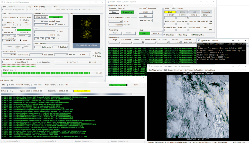
After purchasing XRIT Decoder, USA-Satcom will send you usage instructions that we won't repeat here. The basic steps are to run xrit_decoder.exe, select the SDR, sample rate and mode (LRIT/HRIT), then click on Start Demod. (For GK-2A select COMS-1 LRIT). You can then adjust the gain, and check the Viterbi rate. Like with the initial antenna setup, you can then use Teamviewer and the "Dish Align" feature in XRIT Decoder to fine tune your dish for the lowest Viterbi error rate. USA-Satcom recommends a viterbi rate of below 100, but we've found that under 400 still gives decent results.
Once your viterbi is optimized, go to the GOES XRIT Ingestor screen and click Start. Now you can open xrit_file_manager.exe, and click Start Processing in that window. Over time images will be stored in the "images" folder within the XRIT Decoder folder.
Finally, if you purchased XView, open xview.exe, and set the image path if necessary. Over time the last downloaded image will be displayed.
XRIT Decoder Screens
Example Images that You'll Receive from GOES 16/17 and GK-2A
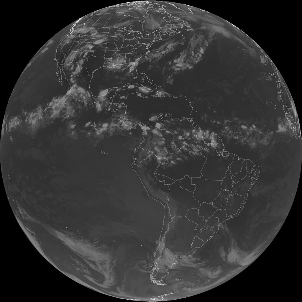
GOES17 Full Disk False Color. Click for the full size image (14MB)Himawari 8 IR Full Disk Relay Image (Infrared) Received from GOES 17GOES 16 Full Disk Relay Received from GOES 17GK-2A LRIT IR Full Disk ImageGOES17 USA ImageNOAA AnalysisNOAA AnalysisNOAA Analysis
SDR-Kits.net have begun selling low cost GPS antennas that are modified to receive the Inmarsat satellite frequencies between 1535 MHz to 1550 MHz. They also have a version for Iridium satellites that receives 1610 MHz to 1630 MHz. The antennas are powered by a 3-5V bias tee, so they should work fine with SDRplay, Airspy and RTL-SDR Blog V3 units.
AERO messages are a form of satellite ACARS, and typically contain short messages from aircraft. It is also possible to receive AERO audio calls. STD-C aka FleetNET and SafetyNET is a marine service that broadcasts messages that typically contain text information such as search and rescue (SAR) and coast guard messages as well as news, weather and incident reports. Some private messages are also seen. To decode AERO Mike uses JAERO, and for STD-C he uses the Tekmanoid STD-C decoder.
Mike has also created a very handy bank of frequencies for the SDRUno frequency manager which can be downloaded from here.
We note that if you're interested in waiting, at the end of September we will have an L-band patch antenna set available too. Our antenna will work from 1525 up to 1637 MHz. Prototypes have shown have shown good Inmarsat, Iridium and GPS reception. More details coming next month when manufacturing gets closer to finishing up.
Screenshot of the Tekmanoid Decoder from Mikes Tutorial
Thank you to Zoltan for submitting a short post about using a moRFeus to uplink WSPR to the Es'Hail-2 (QO-100) geostationary satellite with amateur radio repeater. moRFeus is a versatile US$99 signal generator and frequency mixer that can be controlled either by it's built in LCD screen, or via software on a Windows or Linux PC. It can generate a clean low phase noise tone anywhere between 85 to 5400 MHz, and can be used as a mixer for upconverting or downconverting signals. We have discussed moRFeus a few times before on this blog as we think it's a useful tool.
In his setup, Zoltan uses a QRP Labs U3S WSPR transmitter kit that was configured to transmit WSPR at 2m (144 MHz). It is not designed for transmitting the 2.4 GHz QO-100 uplink frequency. To get around that limitation, the moRFeus is used to upconvert the 144 MHz frequency into the QO-100 uplink band by mixing it with a 2,255,634.309 kHz signal. The resulting 2.4 GHz output signal from moRFeus is sent to an amplifier, 2.4 GHz band pass filter, and finally into a 5-turn LHCP helical feed mounted on a 1m parabolic dish.
Successful uplink was confirmed by a UK based WebSDR receiving the QO-100 downlink. Zoltan estimates that the total output power was only 4mW, and actually more like 1-2 mW due to losses in the coax feed.
Over on YouTube TechMinds has uploaded a video showing how to use the Iridium Toolkit software to receive data and audio from Iridium satellites with an Airspy. Iridium is a global satellite service that provides various services such as global paging, satellite phones, tracking and fleet management services, as well as services for emergency, aircraft, maritime and covert operations too. It consists of multiple low earth orbit satellites where there is at least one visible in the sky at any point in time, at most locations on the Earth.
The frequencies used by the older generation Iridium satellites are in the L-band, and the data is completely unencrypted. That allows anyone with an RTL-SDR or other SDR radio to decode the data with the open source Iridium Toolkit. If you're interested in how Iridium Toolkit was developed, see this previous post about Stefan "Sec" Zehl and Schneider's 2016 talk.
In the video Tech Minds shows decoding of various data, including an audio call and the satellite tracks and heat map of Iridium satellites.
SDR Makerspace is a community based in Greece that is run by the European Space Agency and Libre Space Foundation (who are responsible for the SatNOGS project). It provides funding and resources for Software Defined Radio based space communication projects.
Open-Source SDR Software for Satellite Communications - Alexandru Csete
LimeSDR as an enabler for Satellite TV Transmissions - Dave Crump
How wide band data converters enable SDR in Satcoms - e2v
Teaching SDR: EPFL experience - Bixio Rimoldi
Xilinx’s adaptive solutions for SDR application - Georg Hanak
SDR Makerspace: Evaluation of SDR Boards and Toolchains - Sheila Christiansen
SDR and Amateur radio in space - Michel Burnand
SDR Makerspace lightning talks - Multiple Authors
The second day will consist of workshops on using SDRs for satellite communications, and on using the LimeNET Micro and LimeRFE for SDR satcom development.
Thank you to Frank for submitting his new RTL-SDR compatible Orbcomm Satellite monitor software called "Orbcomm Receiver". Orbcomm is a low earth orbit satellite communications system that operates in the 137 - 138 MHz frequency range. The satellites specialize in remote IoT and machine to machine (M2M) connectivity, an example use case being a GPS tracker on a shipping container regularly uploading GPS coordinates from anywhere in the world via the Orbcomm satellites. Orbcomm satellite signals are fairly strong and can easily be received with an RTL-SDR and V-Dipole antenna.
We haven't posted about Orbcomm on this blog since 2015 since there is not many interesting things to say about it. The data is all encrypted, and the only information you can really see is Orbcomm satellite ID, frequency and positioning data. Franks software doesn't change this fact, but his software is all open source, so it may be a useful tool for learning about satellite signal DSP processing. Frank writes:
There are a couple different projects out there to decode ORBCOMM signals (Orbcomm-Plotter and MultiPSK). What makes my project different from these is that I wrote it as a learning project. So all of the signal processing, written in Python, is available to the user and is decently documented. I hope this can be a good learning resource for people who want to see a practical example of satellite communications signal processing. Also, my software is open source and free to use.
Currently, the software can do offline or real-time decoding of a single ORBCOMM downlink channel. The transmitted bits of the ORBCOMM signal are demodulated and when the packet type is known, the packet information is decoded. There are a lot of ORBCOMM packets that can't be decoded and of course the message data is encrypted so that information is not available. But, there is still a ton of interesting information available.
The project is still in development so it has some limitations. For real-time recordings, I only support RTLSDRs currently. Also, I'm having trouble getting the real-time processing to work on mac OS, so currently that mode is only supported on linux. However, I have included a couple data files in the repo, so even without an SDR, users can experiment with the signal processing. I welcome any bug reports or suggestions.
Over on YouTube Mike Ladd (KD2KOG) from the SDRplay technical support team has uploaded a YouTube video showing him running our recently released RTL-SDR Blog L-Band Active Patch antenna on an SDRplay RSP1a. In the video he receives and decodes AERO signals from his car with his RSP1a powering the active patch antenna via the built in bias tee.
If you didn't already hear, we recently released an active (amplified + filtered) high performance patch antenna designed for receiving L-Band satellites such as Inmarsat, Iridium and GPS. The patch is designed to be easily mountable outside on a window, surface, stick, tree branch etc as it comes with easy to use mounting solutions and extension coax, and is enclosed in a fully weather proof plastic cover. If you're interested the product is available over on our store for US$39.95 with free shipping.
You also might want to keep an eye on Mike's YouTube channel, as he notes that in the yet to be released part 2 video he will be giving away the antenna in a competition.
The Othernet project aims to bring live data such as news, weather, video, books, Wikipedia articles and audio broadcasts to the world via cheap receivers and a free satellite service. Although an internet connection provides the same data, Othernet's satellite broadcast is receivable in remote areas, will continue working in disasters, and costs nothing to continually receive roughly 100-200 MB of data a day. The trade off is that the service is downlink only, so the data that you get is only what is curated by the Othernet team. Currently the service is only available in North America and Europe, but service to other areas in the world may eventuate in the future.
We've posted about this project a few times in the past, as previously they used an L-band satellite service that was received by RTL-SDR dongles. However, these days they operate using LoRa hardware chips on the Ku-band.
Over on YouTube the TechMinds YouTube channel has just uploaded a video that demonstrates the Othernet service being received from the UK via their Dreamcatcher hardware. In particular he shows off the APRS feature which sends any APRS message containing the string "OUTNET" to the Othernet satellite stream. Later in the video he also shows the news articles, weather data, Wikipedia and audio data that was received.