Over on the SDRGPS blog Philip Hahn and fellow aerospace engineer Paul Breed have been working together to try and use an RTL-SDR to help get accurate GPS data for tracking small high powered rockets. They write that their end goal is to be able to “track high power rockets in high acceleration / speed / altitude environments”.
In their latest attempt they launched a rocket with an RTL-SDR on board with it capturing GPS data to be later processed with GNSS-SDR. The goal was to get a GPS fix throughout the flight. Unfortunately they found that a good fix was only obtained while the rocket was on the ground, and not much data was obtained while it was in the air. They write that they suspect that the fault lies in the vibration in the rocket which can affect the frequency stability of the crystal oscillator, or in the GPS satellite tracking loop algorithm.
They still hope to be able to get some usable information from the flight by trying other algorithms on the data, but they are also seeking advice from anyone who might know how to help them, so please contact them if you know anything that may help.
To show that a specialized antenna is not required to receive L-band Inmarsat AERO satellite signals, YouTube user SkyWatcher has uploaded a video showing how he was able to receive these signals with a cheap DVB-T antenna. SkyWatcher writes:
I’ve recently upgraded from my RTL-SDR sticks (E4000, R820T2) to an Airspy Mini.
I did some testing during the last week and found it very interesting that I was able to receive Inmarsat L-Band signals indoors, with just a DVB-T antenna and amplifier behind the window, no downconverter, no special antenna, no super low-noise amplifier. The window is facing south, with a few degrees to the east and the satellite I’ve received was Inmarsat 15.43W. So, angle antenna to satellite should be estimated 20 degrees.
I’ve used a 18dB DVB-T/Satellite-TV inline amplifier as a ‘LNA’ (noise < 5dB) and a VHF/UHF DVB-T antenna which seems to be a stacked dipole, and therefore should be quite wideband and should make a reasonable general purpose antenna. Anyway, I did not expect it to work on 1.5GHZ at all. Also, I want to mention that the inline amplifier is rated 5 to 18V, but it works just fine with the 4.5V from the Airspy Mini.
It seems that with 10dB S/N, Aero reception is possible and with about 12dB S/N, it is getting reliable.
In general, I am very satisfied with the upgrade to the Airspy Mini. It has a much lower noisfloor and a much cleaner spectrum, compared to my old RTL SDRs. Also, I am very happy with the CPU-usage which is only about 12% on my i5-3210M when using 2.4MHz bandwith, and 18-20% with a bandwith of 4.8MHz.
Together with the ability to use SpectrumSpy and the very useful decimation-feature, the Airspy Mini is the best option to upgrade from a RTL-SDR for me at the moment. Anyway, of course this is just my very personal opinion…
AERO is essentially the satellite based version of ACARS, and the L-band signals contains short ground to air messages with things like weather reports and flight plans intended to be transmitted to aircraft. To decode it with an SDR, the JAERO software can be used.
Outernet are a startup company that hope to revolutionize the way people in regions with no, poor or censored internet connectivity receive information. Their service is downlink only, and runs on C and L-band satellite signals, beaming up to date news as well as other information like books, educational videos and files daily. To receive it you will need one of their official or homemade versions of the Lighthouse or Lantern receivers (the latter of which is still to be released), or an RTL-SDR or similar SDR. Recently they began test broadcasts of their new 5 kHz 1539.8725 MHz L-band signal on Inmarsat I4F3 located at 98W (covers the Americas), and they hope to begin broadcasts in more regions soon too.
The typical RTL-SDR is known to often have poor or failing performance above 1.5 GHz (though this can be fixed to some extent), so Outernet have been working on an L-band downconverter. A downconverter works by receiving signals, and shifting them down to a lower frequency. This is advantageous because the RTL-SDR is more sensitive and does not fail at lower frequencies, and if used close to the antenna, the lower frequency allows longer runs of cheap coax cable to be used without significant signal loss.
Earlier this week we received in the mail a prototype of their downconverter. The downconverter uses a 1.750 GHz LO signal, so any signal input into it will be subtracted from this frequency. For example the STD-C frequency of 1.541450 GHz will be reduced to 1750 MHz – 1541.450 MHz = 208.55 MHz. This also means that the spectrum will appear reversed, but this can be corrected by selecting “Swap I & Q” in SDR#. The downconverter also amplifies the signal with an LNA, and has a filter to remove interfering out of band signals.
The prototype Outernet downconverter circuit board.Specsheet for the downconverter.
We tested the downconverter using their patch antenna which they had sent to us at an earlier date (the patch antenna is used and shown in this Inmarsat STD-C reception tutorial). Our testing found that overall the downconverter works extremely well, giving us much better signal levels. Previously, we had used the patch + LNA4ALL and were able to get reception good enough to decode STD-C and AERO signals, but with the requirement that the patch be carefully pointed at the satellite for maximum signal. With the downconverter the signals come in much stronger, and accurate pointing of the patch is no longer required to get a signal strong enough to decode STD-C or AERO.
The downconverter can be powered by a bias tee connection, and this works well with our bias tee enabled RTL-SDR dongles. We also tested with the bias tee on the Airspy R2 and Mini and had no problems. It can also be powered with a direct 5V connection to a header, and they note that the header will be replaced by a USB connector in the production version.
The release date and exact price that these will be sold at is not confirmed, but we believe that it will be priced similarly to upconverters at around $50 USD or less. A good low cost downconverter should help RTL-SDR and other SDR users receive not only the Outernet signal better, but also other satellite signals such as STD-C and AERO. Although the input is filtered and the RF frequency is specified at 1525 to 1559 MHz, we had no trouble receiving signals up to GPS frequencies of 1575 MHz, and even up to Iridium signals at 1.626 GHz, though reception was much weaker up that high.
Below are some screenshots of reception. Here we used the Outernet patch antenna sitting in a windowsill with the downconverter directly after the antenna, and then 10 meters of RG6 coax cable to the PC and bias tee enabled RTL-SDR. We found that with the downconverted ~200 MHz signal the loss in the RG6 coax was negligible. Better reception could be obtained by putting the patch outdoors. In some screenshots we used Vasilli’s R820T driver with the decimation feature, which allows you to zoom into narrowband signals much more clearly.
Some AERO Signals Zoomed in with the Decimation feature in SDR#. Received with the Outernet downconverter and patch antenna.Some AERO and other Signals Zoomed in with the Decimation feature in SDR#. Received with the Outernet downconverter and patch antenna.Signals zoomed out. Received with the Outernet downconverter and patch antenna.
Over the last few weeks Adam 9A4QV has been testing L-Band Inmarsat reception with his LNA4ALL low noise amplifiers. In a previous post he tested reception with two LNA4ALL and found that he got an improved SNR ratio over using just one LNA4ALL. In his latest video he tests Inmarsat reception with three LNA4ALL’s and two L-band filters. His results show that the SNR is improved over using two LNA4ALL’s, and can almost match the results obtained by a commercial L-band front end which he also demonstrated in a previous video.
Back in April we posted about Philip Hahn and Paul Breed’s experiments to use an RTL-SDR for GPS logging on their high powered small rockets. As GPS is owned by the US military, a standard GPS module cannot be used on a rocket like this, as they are designed to fail if the GPS device breaches the COCOM limit, which is when it calculates that it is moving faster than 1,900 kmph/1,200 mph and/or higher than 18,000 m/59,000 ft. The idea is that this makes it harder for GPS to be used in non-USA or home made intercontinental missiles. As SDR GPS decoders are usually programmed in open source software, there is no need for the programmers to add in these artificial limits.
In their last tests they managed to gather lots of GPS data with an RTL-SDR, but were only able to decode a small amount of it with the GNSS-SDR software. In this post Philip discoversa flaw in the way the GNSS-SDR performs acquisition and retrackingthat GNSS-SDR decodes in such a way that makes it difficult to obtain a location solution with noisy high-acceleration data. By using a different GPS implementation coded in MATLAB, he was able to get decoded GPS data from almost the entire ascent up until the parachutes deploy. Once the parachutes deploy the GPS has a tough time keeping a lock as it sways around. His post clearly explains the differences in the way the code is implemented in GNSS-SDR and in the MATLAB solution and shows why the GNSS-SDR implementation may not be suitable for high powered rockets.
In addition, they write that while the flight was just under the artificial COCOM GPS fail limits for speed and height, the commercial GPS solution they also had on board failed to collect data for most of the flight too. With the raw GPS data from the RTL-SDR + some smart processing of it, they were able to decode GPS data where the commercial solution failed.
GPS data acquired from the RTL-SDR on the rocket (blue line shows solution from MATLAB code, yellow shows GNSS-SDR solution, and red shows commercial GPS receiver solution).
A few days ago we posted a review on the Outernet LNA which can can be used to help receive their new L-band service signal. Their LNA uses a filter which restricts the frequency range from 1525 – 1559 MHz as this is the range in which the Outernet signals are located.
Additional Note Regarding the Downconverter: Also, it appears that the Outernet downconverter prototype that we posted about back in May has unfortunately been discontinued indefinitely and will not enter mass production. For now the LNA is the best option for receiving their signal.
At this year’s hacker themed Eleventh Hope conference, Stefan “Sec” Zehl and Schneider gave a talk which discusses their latest work on decoding data from Iridium satellites using SDR’s. Iridium is a truly global satellite service which provides various services such as global paging, satellite phones, tracking and fleet management services, as well as services for emergency, aircraft, maritime and covert operations too. There are currently 72 operational satellites operating.
In their talk they discuss how Iridium security is moderate to relaxed, pointing out that Iridium claims that the majority of ‘security’ comes from the complexity of the system, rather than actual security implementations. They then go on to discuss how the Iridium system works, how to receive it with an RTL-SDR or HackRF/Rad1o, how the gr-iridium decoder implementation works, and how to use it to actually decode the data. Later in the presentation they show some interesting examples such as an intercepted Iridium satellite phone call to a C-37 aircraft.
Outernet is a new L-band satellite services which aims to be a “library in the sky”. Their satellite signal can be received from almost anywhere in the world, and they aim to constantly transmit data like news, weather updates, books, images/videos and other data files. The service is free and can be received with an RTL-SDR, LNA and patch antenna. We have a full tutorial on receiving their service available here.
The “rxOS” decoder, file management system and web interface GUI has recently been updated to version 3.0. This new version has several new features:
Downloaded files are automatically decompressed after downloading, so they can be viewed directly in the Outernet web interface.
An hourly transmission of APRS data which comes from the repeater on board the international space station. APRS messages can now be relayed across the world via the ISS and Outernet.
This Monday they will begin transmitting NOAA weather data (we are unsure if this entails images or text data yet)
Soon they should begin transmitting news data too.
More details on the update can be found on their forum post. To update the service on a CHIP or Pi 3, download the .pkg file from the links on the forum and choose this file in the Update Firmware section of the Outernet settings menu.
An example of some received APRS messages from the Outernet.APRS messages
Outernet is a satellite based file delivery service. Currently they’re beta testing their service and they are using RTL-SDR’s as the receiver. In previous posts we’ve seen that they’re now regularly transmitting weather updates, wikipedia files and more files like images and books. Over time the service is becoming more and more useful. If you’re interested in receiving their service we have a tutorial available here.
While most of the Outernet software is open sourced, the signal protocol itself is closed source, which ties you into needing to use the official Outernet software. Over on his blog, Daniel Estévez has been working on reverse engineering the Outernet signal with the goal of publishing the results and building a fully open source receiver.
So far he’s managed to fully reverse engineer the modulation, coding and framing. He’s also been able to build a GNU Radio program that receives the Outernet frames and a Python program called free-outernet which does the decoding. His post goes into greater details on how he reverse engineered the signal and what his finding are.
Many people with an RTL-SDR have had fun receiving NOAA and METEOR low earth orbit (LEO) weather satellite images. However, a step up in difficulty is to try and receive the geostationary orbit (GEO) weather satellites like GOES. These satellites are locked to a fixed position in the sky meaning there is no need to do tracking, however since they are much further away than LEO satellites, they require a 1m+ satellite dish or high gain directional antenna to have a chance at receiving the weak signal. The GOES satellites transmit very nice high resolution full disk images of the earth, as well as lots of other weather data. For more information see this previous post where we showed devnulling’s GOES reception results, and this post where we showed @usa_satcom’s presentation on GOES and other satellites.
The nice thing about Lucas’ post is that he documents his entire journey, including the failures. For example after discovering that he couldn’t find a 1.2m offset satellite dish which was recommended by the experts on #hearsat (starchat), he went with an alternative 1.5m prime focus dish. Then after several failed attempts at using a helix antenna feed, he discovered that his problem was related to poor illumination of the dish, which meant that in effect only a small portion of the dish was actually being utilized by the helix. He then tried a “cantenna”, with a linear feed inside and that worked much better. Lucas also discovered that he was seeing huge amounts of noise from the GSM band at 1800 MHz. Adding a filter solved this problem. For the LNA he uses an LNA4ALL.
To position the antenna Lucas used the Satellite AR app on his phone. This app overlays the position of the satellite on the phone camera making it easy to point the satellite dish correctly. He also notes that to improve performance you should experiment with the linear feeds rotation, and the distance from the dish. His post of full of tips like this which is very useful for those trying to receive GOES for the first time.
In future posts Lucas hopes to show the demodulation and decoding process.
GOES signals received with the dish, LNA4ALL, filter and an Airspy.
Last week we posted about Lucas Teske’s (@lucasteske) experience with setting up an antenna system that can receive the geostationary GOES weather satellites. He set up a dish antenna, feed, LNA and filter and was able to successfully receive the GOES signal with an RTL-SDR and Airspy.
Now Lucas has uploaded his second post where he discusses how to demodulate the GOES signal. The GOES satellites transmit a Low-Rate Information Transmission (LRIT) signal which contains full disk images of the earth as well as other weather data from the secondary Emergency Managers Weather Information Network (EMWIN) signal.
In order to demodulate the signal Lucas wrote a BPSK demodulator in GNU Radio. His post goes into good technical detail and shows exactly how the demodulator is constructed. Basically the the BPSK signal is first decimated down to 2.5e6, normalized with an AGC, then cleaned up with a Root Raised Cosine Filter. From there the signal goes through a Costas Loop PLL to receover the carrier wave, then a Clock Recovery MM block to recover the symbol clock. The data is then output to a TCP pipe for the decoder.
In the upcoming third part of his article Lucas will show us how to actually turn the demodulated data into an image of the earth.
Yesterday we posted about Lucas Teskes (@lucasteske) success in building a demodulator for the GOES weather satellite. Before that he also showed us how to build an antenna system to receive GOES with an Airspy or RTL-SDR dongle.
Today Lucas continues with part three of his series on GOES decoding. This time he shows how he has built a frame decoder to process the output of the demodulator, and also gives us a link to his code. The decoder is written in C code. Lucas’ post explains how to sync the frame by detecting the preamble, perform convolution encoding to generate a parity and help correct any errors, and decode the frame data.
In part four Lucas will show us how to parse the frame data and extract the packets which will eventually form an image file of the earth.
A decode frame viewed as an image. This shows the syncword pattern and frame counter.
In his latest two posts Lucas Teske continues with his series about receiving and downloading weather satellite images from the GOES satellites. In past posts he’s show us how to receive the signal with a satellite dish and Airspy or RTL-SDR (part 1), how to demodulate the signal (part 2), and how to extract frames from the demodulated signal (part 3). Lucas has recently completed his series with parts 4 and 5 having just been uploaded.
In part 4 Lucas shows how to parse the frames and get the packets which will ultimately be used to generate the weather image files. His post explains how to de-randomize the frame data which is initially randomized to improve performance, how to add Reed Solomon error correction, how to demux the virtual channels and the packets and finally how to save the raw packet.
The packet structure
In part 5 Lucas shows us how to finally generate weather satellite images from the GOES satellites. He notes that there is a problem with the LritRice compression method used by NOAA, because the library is currently broken on Linux. So he made a workaround which involved making a Windows application that runs through Wine for decompressing the data. Once the files are decompressed he uses the xrit2pic program which can open the generated .lrit files and convert them into images.
In the future Lucas mentions that he will write a user guide to his LRIT decoder, and make the whole decoding process more user friendly for people who do not care so much about the actual decoding process. Below are some images that Lucas was able to receive with his system.
GOES Full Disk Image of the EarthWeatherfax (WEFAX) Image
Outernet is a relatively new satellite based file delivery service which can be received with an RTL-SDR dongle. They continuously send out useful data like weather reports, news, APRS data as well as files like Wikipeda pages, images, videos and books. Previously we posted a tutorial that shows how to set up an Outernet receiver here.
If you instead prefer video tutorials, then two YouTube channels have uploaded Outernet set up tutorials. The first tutorial is by MKme Lab. In this video they set up Outernet using a Raspberry Pi and a Lipo battery for portable operation. Once setup he shows the Outernet browser and weather app in action.
The second video is by John’s DIY Playground and is similar, but goes a bit deeper into setting up the software on the Raspberry Pi and shows how to point the patch antenna towards the satellite.
Akos from the radio for everyone blog (formerly known as the rtlsdr4everyone blog) has uploaded two new posts. On the first post he shows some further tests on the new FlightAware Prostick plus. The Prostick is an RTL-SDR that contains a built in LNA and the Prostick plus adds an additional SAW filter on the stick. For him the Prostick Plus works significantly better than the regular Protstick + external FA cavity filter and also gets about twice the ADS-B reception reports as our V3 which does not use an additional internal LNA. Next week we hope to release our own review of the Prostick Plus, and we’ll hopefully be able to show and explain why some people see better performance with the plus and why some instead see degraded performance.
In his second post Akos shows a tutorial on building an easy helical antenna for Outernet reception. The antenna is constructed from readily available household materials such as a soda bottle, coax cable, electrical tape and a cookie tin. With the cookie tin used he was able to get a SNR reading between 7 – 9 dB, which is pretty good considering that only 3 dB is required for Outernet decoding to work.
Outernet hardware plus the homemade helical antenna made by Akos.
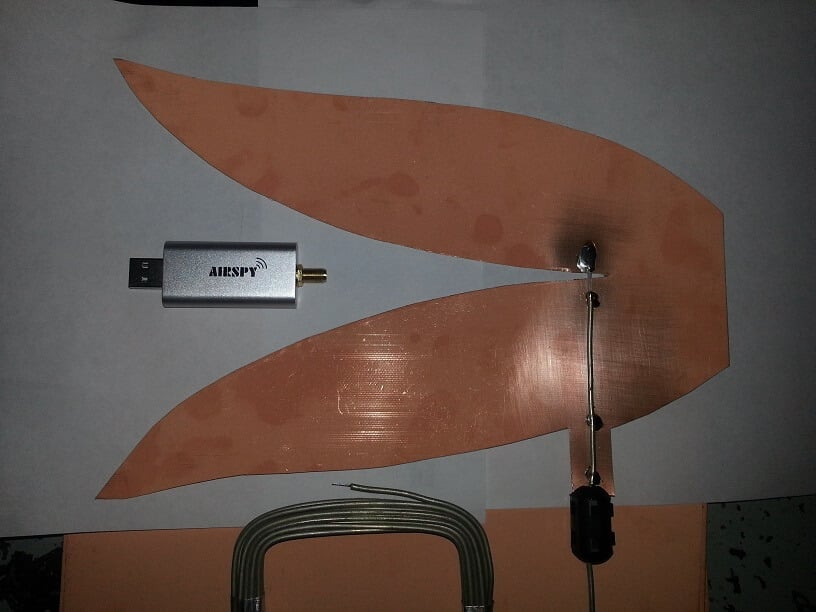
Vivaldi’s are linearly polarized broadband antennas that have a directional radiation pattern at higher frequencies. The high end SDR manufacturer RF Space produces their own Vivaldi antennas made from PCB boards which they sell online. The larger the antenna, the lower its receiving frequency, and ones that go down to about 200 MHz are almost the size of a full adult person. But all sizes receive up to 6 GHz maximum. Typically smaller versions of Vivald antennas have been used in the past for L-Band satellite reception.
Over on his blog KD0CQ noted that he always had trouble trying to purchase a Vivaldi from RF Space because they were too popular and always out of stock. So he decided to try and build his own out of PCB boards. On this page he’s collected a bunch of Vivaldi cutout or transfer images. On his second page he shows a Vivaldi antenna that he built out of PCB material, just by using scissors and semi-rigid coax. With the Vivaldi placed outdoors he’s been able to successfully receive and decode L-Band AERO on his Airspy Mini even without an LNA.
KD0CQ writes that he’ll update his blog soon with more results.
Simple Vivaldi antenna by KD0CQ cut out of PCB board.
BY70-1 is a Chinese amateur Cubesat satellite which was recently launched on December 29, 2016. It is expected to stay in orbit for only 1 – 2 months due to a partial failure with the satellite releasing into an incorrect orbit. The purpose of the satellite is for education in schools and for amateur radio use. The receivable signals include an FM repeater and BPSK telemetry beacon both of which can be received at 436.2 MHz. The telemetry beacon is interesting because it also transmits images from an on board visible light camera. These signals can easily be received with an RTL-SDR or other SDR with an appropriate antenna.
Over on his blog Daneil Estevez has been posting about decoding these telemetry images. He’s been using telemetry data collected by other listeners, and the gr-satellites GNU Radio decoder which is capable of decoding the telemetry beacons on many amateur radio satellites. So far the decoded images haven’t been great, they’re just mostly black with nothing really discernible. Hopefully future decodes will show better images.
If you want to track the satellite and attempt a decode, the Satellite AR Android app has the satellite in its database.
Not many people seem to have gotten telemetry decodes or images yet, but below we show an image decoded by @bg2bhc on Twitter.
Over on YouTube user Tomi Simola has uploaded a video showing his servo based Outernet satellite antenna tracker. Outernet uses L-band geostationary satellites which means that they are at a fixed position in the sky. Optimal reception of the Outernet and other L-Band satellite signals can be obtained by pointing the patch antenna towards the satellite.
Tomi wanted an easy way to remotely switch the antenna to point at one of two geostationary satellites, Alphasat at 25E which has the Outernet signal and Inmarsat at 64E which has more services like AERO and STD-C. Another potential use of his tracker might be for tracking L-Band satellite while in a moving vehicle such as a car or boat.
To automatically point the Outernet L-band patch antenna Tomi used a commonly found Pan-Tilt servo mounted inside an waterproof enclosure. On the servo is a 3D printed mount which the patch antenna is attached on. An Arduino Nano with Bluetooth module allows control of the servo.
GOES is an L-band geosynchronous weather satellite service that can be received typically with a satellite dish. It produces very nice full disk images of the earth. In the past we’ve posted about Lucas Teske’s work in building a GOES receiving system from scratch (including the software decoder for Airspy and RTL-SDR receivers), devnullings post about receiving GOES and also this talk by @usa_satcom on decoding GOES and similar satellites.
Over on Twitter @usa_satcom has been tweeting about his experiments where he has been successfully receiving GOES L-Band weather satellite images with a small grid antenna and an Airspy Mini. In a Tweet he writes that the antenna is an $85 USD Hyperlink 1.9 GHz 22 dBi Grid Antenna made by L-com. A grid antenna may be more suitable for outdoor mounting for many people as they are typically lighter, smaller and more suitable for windy and snowy conditions. As the GOES satellite is in geosynchronous orbit, no tracking motor or tracking mount is required.
GOES LRIT on small grid antenna? Sure, works just fine! Just a test setup for now. I'll post some FFTs and actual images later. pic.twitter.com/U6fALGCHl2
Back in October/November of last year Lucas Teske showed us how to receive weather satellite images from the GOES line of geostationary satellites with an Airspy SDR (and possibly an RTL-SDR too), dish antenna and the decoding software that he created.
On November 19, 2016 the next generation GOES 16 (aka GOES-R) satellite was launched by NASA. GOES 16 is a little different to the older GOES satellites as it has better sensors and is capable of capturing and transmitting a new image every 15 minutes which is quite fast. Thus a different and higher bandwidth RF transmission protocol called HRIT (High Rate Information Transfer) is used, compared to the LRIT (Low Rate Information Transfer) signal used on the older satellites.
Once the satellite started transmitting in January 2017, Lucas got to work on trying to create a decoder for the new satellite. After noticing some discrepancies between the published HRIT specs and the actual signal, Lucas sent off an email to NOAA and actually received an email back with the full specifications. With this information he was able to update his Open Satellite Project code and start decoding images from GOES 16.
The images being sent right now seem to just be relays of other similar satellites like Himawari-8 and Meteosat, as it seems that they are still testing the satellite. The relayed images received via GOES 16 received by Lucas can be seen on the Open Satellite Project twitter feed and on Lucas’ personal twitter feed.
Full disk image received via GOES 16, relayed from the Himawari-8 satellite.Weather data received via GOES 16.